Receiver und (Vor-)Verstärker außerhalb atelier/regie/slim line
-
skvuppla
- Jungspund

- Beiträge: 25
- Registriert: 14.12.2010, 09:19
#1
Beitrag
von skvuppla » 06.01.2011, 21:03
Hi
I'm having problems with my CSV 510. There's no sound in one channel (the right). I can't find any visual problems everything looks nice... If I turn the volume up all the way I can here low music in the channel. The left channel seems to work fine.
There might be a problem with the input selector, when I use the band input it doesn't matter which input I select, there's always music (in the left channel). Plus the power lamp only lights sometimes....
If you have a clue about what the problem might be please help...

regards
-
Wilhelm
- Braun-Freak

- Beiträge: 862
- Registriert: 19.01.2009, 03:06
- Wohnort: Mount Forest, Kanada
#2
Beitrag
von Wilhelm » 06.01.2011, 21:48
Hi skvuppla,
the light bulb is either loose in the socket or on the "blink" (replacement 18V 0.1A). By the way, try switching to mono ... any sound in the right channel? Don't forget the amp is more than 40 years old and there could be all kinds of faulty components. Maybe you should have it checked by a technician.
Regards
Wilhelm
If you need the schematics let me know.
-
skvuppla
- Jungspund
- Beiträge: 25
- Registriert: 14.12.2010, 09:19
#3
Beitrag
von skvuppla » 06.01.2011, 22:12
switching to mono doesn't make a difference, same problem..
unfortunately I can't afford a technician will cost up to 100€ per hour here in denmark and the amplifier only costed 30€
the light-bulb seems fine, I´ve tested it with my multimeter, but if i try to messure the voltage on the lightsocket I get less than a volt
-
skvuppla
- Jungspund
- Beiträge: 25
- Registriert: 14.12.2010, 09:19
#4
Beitrag
von skvuppla » 06.01.2011, 22:33
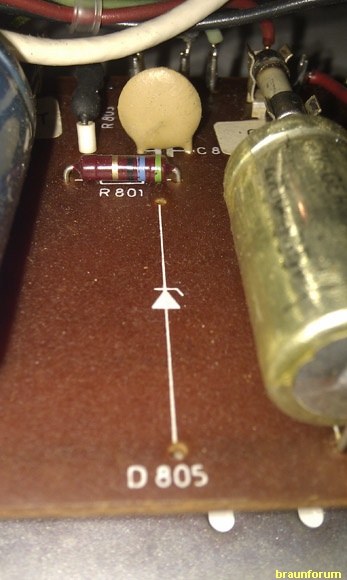
I've noticed there's a component missing.. what's supposed to be here?
-
Wilhelm
- Braun-Freak
- Beiträge: 862
- Registriert: 19.01.2009, 03:06
- Wohnort: Mount Forest, Kanada
#5
Beitrag
von Wilhelm » 06.01.2011, 22:43
Sorry,
but I can't help you with the broken right channel and any repair will involve some cost. To the best of my knowledge there are no specific flaws in the CSV 510 circuitry.
It doesn't make any sense that you measure less than one volt. The voltmeter must be set to AC! The light bulb is connected directly to the secondary winding of the transformer via a fuse and a 100 Ohm resistor. The fuse must be okay, otherwise your preamp wouldn't be working (left channel) at all. Again, if you need the schematics let me know.
Regards
Wilhelm
-
Wilhelm
- Braun-Freak
- Beiträge: 862
- Registriert: 19.01.2009, 03:06
- Wohnort: Mount Forest, Kanada
#6
Beitrag
von Wilhelm » 06.01.2011, 22:54
skvuppla hat geschrieben:
I've noticed there's a component missing.. what's supposed to be here?
There is no missing part. The zener-diode was used only in the CSV500 and Braun used the same power supply board for the CSV510.
Regards
Wilhelm
-
skvuppla
- Jungspund
- Beiträge: 25
- Registriert: 14.12.2010, 09:19
#7
Beitrag
von skvuppla » 07.01.2011, 11:32
Thanks for the help Wilhelm. Since there's no component missing I guess I'm really in need for the schematics and service manual. I couldn't find it in the link you sent me earlier though
-
Wilhelm
- Braun-Freak
- Beiträge: 862
- Registriert: 19.01.2009, 03:06
- Wohnort: Mount Forest, Kanada
#8
Beitrag
von Wilhelm » 07.01.2011, 14:22
Hi,
sorry, I did post the wrong link. I will send you a pn today.
Regards
Wilhelm
-
jsbo
- Experte

- Beiträge: 297
- Registriert: 07.05.2009, 23:40
- Wohnort: 448XX Bochum
#9
Beitrag
von jsbo » 08.01.2011, 16:44
skvuppla hat geschrieben:Thanks for the help Wilhelm. Since there's no component missing I guess I'm really in need for the schematics and service manual. I couldn't find it in the link you sent me earlier though
schematics and service manual you find
on:
REGIE 510
Jürgen
Tief im Westen...............................................
-
Wilhelm
- Braun-Freak
- Beiträge: 862
- Registriert: 19.01.2009, 03:06
- Wohnort: Mount Forest, Kanada
#10
Beitrag
von Wilhelm » 08.01.2011, 19:07
Hello Juergen,
he is looking for the schematics of a CSV510 not regie510, I made the same mistake. I did notify him (pn) that I do have the right one but he hasn't responded yet.
Regards
Wilhelm
-
skvuppla
- Jungspund
- Beiträge: 25
- Registriert: 14.12.2010, 09:19
#11
Beitrag
von skvuppla » 08.01.2011, 20:23
Wilhelm hat geschrieben:Hello Juergen,
he is looking for the schematics of a CSV510 not regie510, I made the same mistake. I did notify him (pn) that I do have the right one but he hasn't responded yet.
Regards
Wilhelm
sorry wilhelm. I don't know what pn is.
-
Wilhelm
- Braun-Freak
- Beiträge: 862
- Registriert: 19.01.2009, 03:06
- Wohnort: Mount Forest, Kanada
#12
Beitrag
von Wilhelm » 08.01.2011, 20:32
Hi,
pn means "persoenliche oder private Nachricht" or "personal message."
Regards
Wilhelm
If you have problems reading the "pn" let me know.
-
Norbert
- Gründer (inaktiv)
")
- Beiträge: 2047
- Registriert: 02.01.2009, 19:27
- Wohnort: 79106 Freiburg
#13
Beitrag
von Norbert » 08.01.2011, 20:39
skvuppla hat geschrieben:sorry wilhelm. I don't know what pn is.
Hi,
simply click on the button "pn" at the bottom in the message window from Wilhelm. Than it works fine, just type your message and send it away

Only Wilhelm can read your message, it's private.
Regards, Norbert
Wenn es nach dem Löten kracht, hast du etwas falsch gemacht.
Nostalgie Funk - le groove de légende
-
skvuppla
- Jungspund
- Beiträge: 25
- Registriert: 14.12.2010, 09:19
#14
Beitrag
von skvuppla » 28.01.2011, 13:50
Hi again
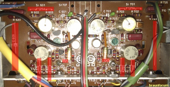
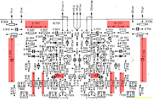
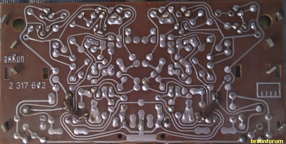
I´ve noticed some differences between my power circuit and the one in the schematics the pcb number is also different mine is 2317602 in schematics its 2317603..
Are these modifications or is my amp just another version?? and could it explain the non working channel?
its the channel on the left that's not working, the one with blue and red cables
-
Wilhelm
- Braun-Freak
- Beiträge: 862
- Registriert: 19.01.2009, 03:06
- Wohnort: Mount Forest, Kanada
#15
Beitrag
von Wilhelm » 29.01.2011, 19:12
Hi Juergen,
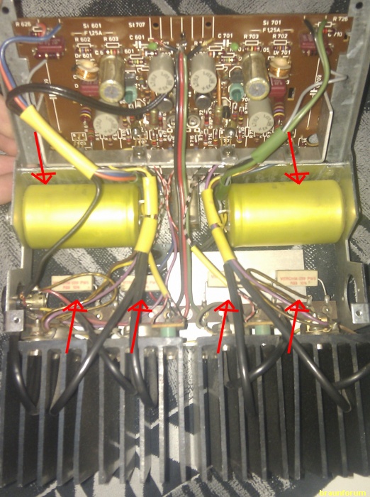
Somebody must have modified your power amp. According to your pictures, there are no fuses on the board and no capacitors in the output stage. Somebody must have mounted the capacitors C609, C709 in a different spot otherwise this kind of amp would blow your speakers in a second (high DC voltage). In addition, the power stage should be refused, Si601, 701.
Nevertheless, when one channel is working so should the other one. I did notice the old Roederstein capacitors (red or gray, looking almost like flower pots), these should definitely be replaced. As a matter of fact, you should replace all of the old caps. Old capacitors dry out and can cause all sort of problems.
Personally,I would rebuild the amp to the original configuration (see circuit diagram).
Regards
Wilhelm
-
skvuppla
- Jungspund
- Beiträge: 25
- Registriert: 14.12.2010, 09:19
#16
Beitrag
von skvuppla » 30.01.2011, 10:54
hi wilhelm
I have a problem rebuilding the amp, I don't know what parts I need ( only have the numbers you see on pcb and on schematics).
I don't know if you have noticed the resistor on the backside of the pcb, is this part of a mod too? it combines R622/R722 to C605/C705 i think...
The missing capacitors c609/c709 I can't find, they must have been removed.
-
Wilhelm
- Braun-Freak
- Beiträge: 862
- Registriert: 19.01.2009, 03:06
- Wohnort: Mount Forest, Kanada
#17
Beitrag
von Wilhelm » 30.01.2011, 17:54
Hi,
for the power amp to work properly (without these capacitors) the entire circuit, including the power supply, would have to be changed. The voltage for the power amp is 65VDC, this means, without C609,C709 half of the DC voltage would go to the speakers. This would destroy them and totally overload the output stage (in best case scenario, the fuses would blow).
The resistors on the backside are also part of the modification.
In order to reverse everything to its original stage you would have to check every component and replace the missing or changed parts according to the schematics.
Regards
Wilhelm
-
skvuppla
- Jungspund
- Beiträge: 25
- Registriert: 14.12.2010, 09:19
#18
Beitrag
von skvuppla » 30.01.2011, 22:10
but in the schematics every component is just given a number, how do I know what component the number symbolises?
-
Norbert
- Gründer (inaktiv)
- Beiträge: 2047
- Registriert: 02.01.2009, 19:27
- Wohnort: 79106 Freiburg
#19
Beitrag
von Norbert » 30.01.2011, 22:35
skvuppla hat geschrieben:but in the schematics every component is just given a number, how do I know what component the number symbolises?
Hi,
do you have the completely circuit diagram for the CSV 510 or only the layouts? In the circuit diagram every component has a position number and data.
Regards, Norbert
Wenn es nach dem Löten kracht, hast du etwas falsch gemacht.
Nostalgie Funk - le groove de légende
-
simon
- Profi

- Beiträge: 462
- Registriert: 01.02.2010, 18:20
- Wohnort: Bremen
#20
Beitrag
von simon » 30.01.2011, 22:48
Hi skvuppla,
if nobody here provides you/us with the CV 510 circuit diagram of the Braun CSV 510 (not the pcb layout), your residual chance is the reconstruction of the broken right channel based on your measurements of the working left channel.
The mentioned modifications seem to be so called "High End" motivated. I agree to Wilhelm that eventually you should go back to the Braun-roots to be on the safe side.
Anyway, if the left channel of your amplifier works fine (with or without the capacitors) , it should not be excessively difficult to find the problem of the right channel.
Good luck! Simon
-
skvuppla
- Jungspund
- Beiträge: 25
- Registriert: 14.12.2010, 09:19
#21
Beitrag
von skvuppla » 30.01.2011, 22:59
unfortunately I only have the layout and not the complete circuit diagram
-
Wilhelm
- Braun-Freak
- Beiträge: 862
- Registriert: 19.01.2009, 03:06
- Wohnort: Mount Forest, Kanada
#22
Beitrag
von Wilhelm » 31.01.2011, 00:21
Hi Juergen,
why do you have only the layout? I did email you the complete service manual!
Regards
Wilhelm
-
skvuppla
- Jungspund
- Beiträge: 25
- Registriert: 14.12.2010, 09:19
#23
Beitrag
von skvuppla » 31.01.2011, 09:56
yes I do... I just starred at the pcb layout...

-
simon
- Profi
- Beiträge: 462
- Registriert: 01.02.2010, 18:20
- Wohnort: Bremen
#24
Beitrag
von simon » 01.02.2011, 08:23
Hi skvuppla,
Wilhelm kindly forwarded the Service Instructions to me (Thank you, Wilhelm!).
The last pages (12, 13, 14) indeed show the complete circuit diagram ("Stromlaufplan").
There you should easily identify the data you look for. Let me know if I may help you.
Best whishes from Bremen, Simon
-
skvuppla
- Jungspund
- Beiträge: 25
- Registriert: 14.12.2010, 09:19
#25
Beitrag
von skvuppla » 01.02.2011, 12:01
Thank you. I have got the Stromlaufplan in even better quality now (different scan) if you're interested.
I've looked the schematics through now and what I see R 719, 721 is removed and also C709 and the fuse Si 701
The capacitor C703 has been relapsed with a 04.71 ROE connecting between R704 and R705
The resistors on the back to me seems to be original (R727), but they are not shown on the PCB only in the Stromlaufplan
The Transistors T 709 and T708 there's nothing connected to E.. at least not what I can see.. Are T708 and 709 the ones on the heatsink?
All other components looks original
-
skvuppla
- Jungspund
- Beiträge: 25
- Registriert: 14.12.2010, 09:19
#26
Beitrag
von skvuppla » 01.02.2011, 12:30
and an other question
the missing capacitors c709 and c609 what voltage are they?
and the replaced c703 and c603
-
skvuppla
- Jungspund
- Beiträge: 25
- Registriert: 14.12.2010, 09:19
#27
Beitrag
von skvuppla » 01.02.2011, 22:56
well i found the missing components...
and now I finally understand what the dotted line on the schematics means
And im still not sure if the capacitors C703 and c603 are connected correctly..
regards
anders (getting dumber by the day)
-
Wilhelm
- Braun-Freak
- Beiträge: 862
- Registriert: 19.01.2009, 03:06
- Wohnort: Mount Forest, Kanada
#28
Beitrag
von Wilhelm » 01.02.2011, 23:53
It seems to me that the capacitors C603,C703 are currently connected to R625,725 which is not according to the schematics. Remove and solder them into the pcb according to the original layout (the correct place is clearly marked).
Regards
Wilhelm
Have a look whether you can find the fuses (Si601,701)!! The power amp should be fused. By the way, I have to apologize, when I looked at the picture I remembered that C609/709 are not mounted on the board instead they are mounted on the chassis.
-
skvuppla
- Jungspund
- Beiträge: 25
- Registriert: 14.12.2010, 09:19
#29
Beitrag
von skvuppla » 02.02.2011, 08:57
Wilhelm hat geschrieben:It seems to me that the capacitors C603,C703 are currently connected to R625,725 which is not according to the schematics. Remove and solder them into the pcb according to the original layout (the correct place is clearly marked).
Regards
Wilhelm
Have a look whether you can find the fuses (Si601,701)!! The power amp should be fused. By the way, I have to apologize, when I looked at the picture I remembered that C609/709 are not mounted on the board instead they are mounted on the chassis.
yes, the capacitors C603,C703 are currently connected to R625,725 I will try to buy new ones today and solder them according to the original layout.
The fuses (Si601,701) aren't "fuses" they are heatswitches on the transistors on the heatsink. I have tested them with my multimeter and I think they are ok
-
skvuppla
- Jungspund
- Beiträge: 25
- Registriert: 14.12.2010, 09:19
#30
Beitrag
von skvuppla » 02.02.2011, 15:27
can bad caps be the cause of the left channel not working? And when you say all caps should be replaced do you mean ALL or just the electrolytic ones?
I've also noticed today that the volume is pretty low even in the working channel.